Drawing
How to draw an electrical plan
The Electrical tool places standard electrical symbols on your plan: switches, outlets, lights, fans, alarms, a panel and data outlets. The Wire tool then connects them, so you can show which switch runs which light, or which outlets share a circuit.
Use it to plan a renovation, brief an electrician or document the wiring of a house you already own.
Place electrical symbols
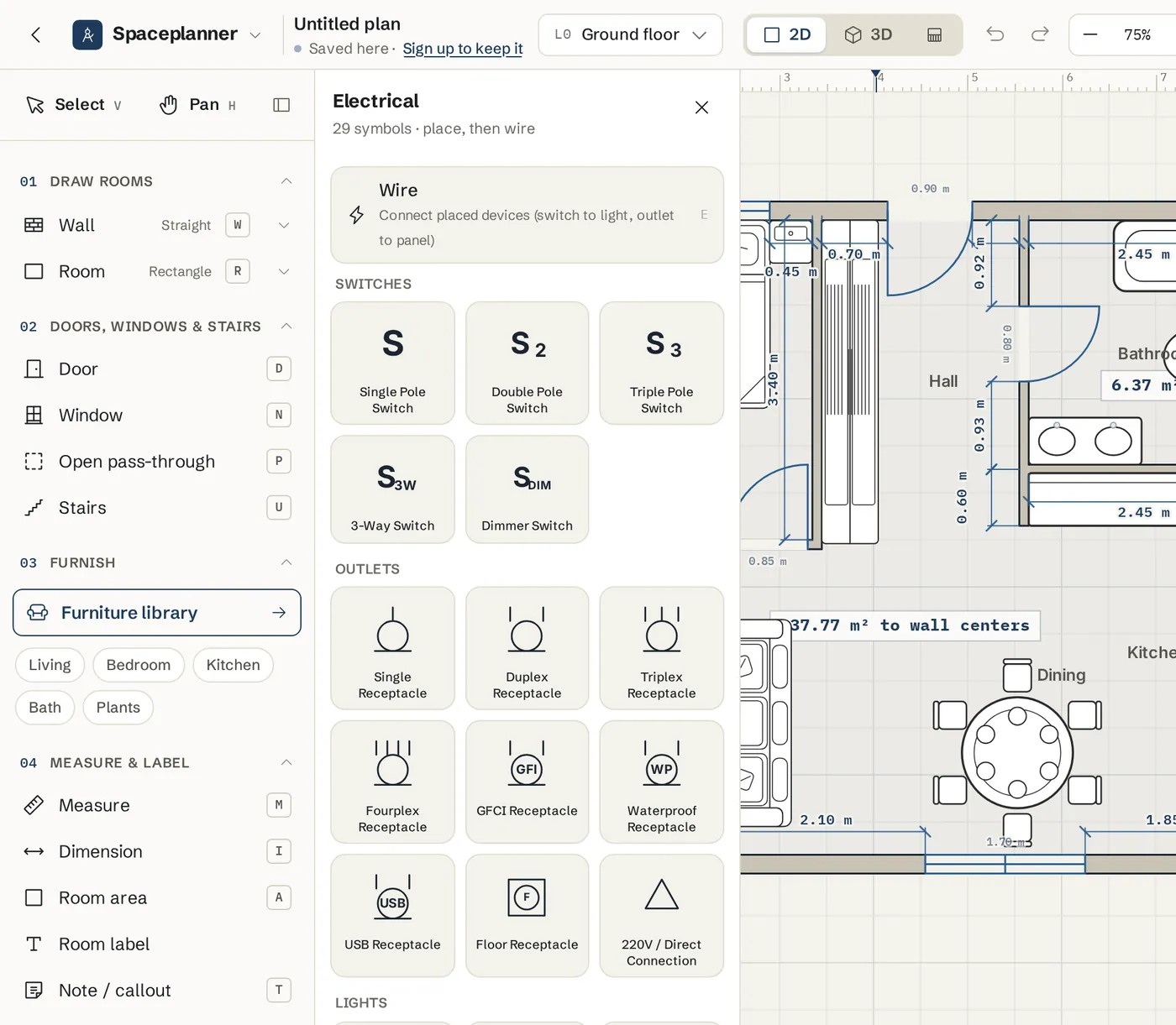
Open the Electrical panel
Press C, or click Electrical in the left toolbar under Electrical. The Electrical panel opens with its symbols grouped as Switches, Outlets, Lights, Alarms and Distribution & data.
Pick a symbol
Click a symbol, for example Duplex Receptacle, Single Pole Switch, Recessed Light, Smoke Detector or Electrical Panel.
Click the plan to place it
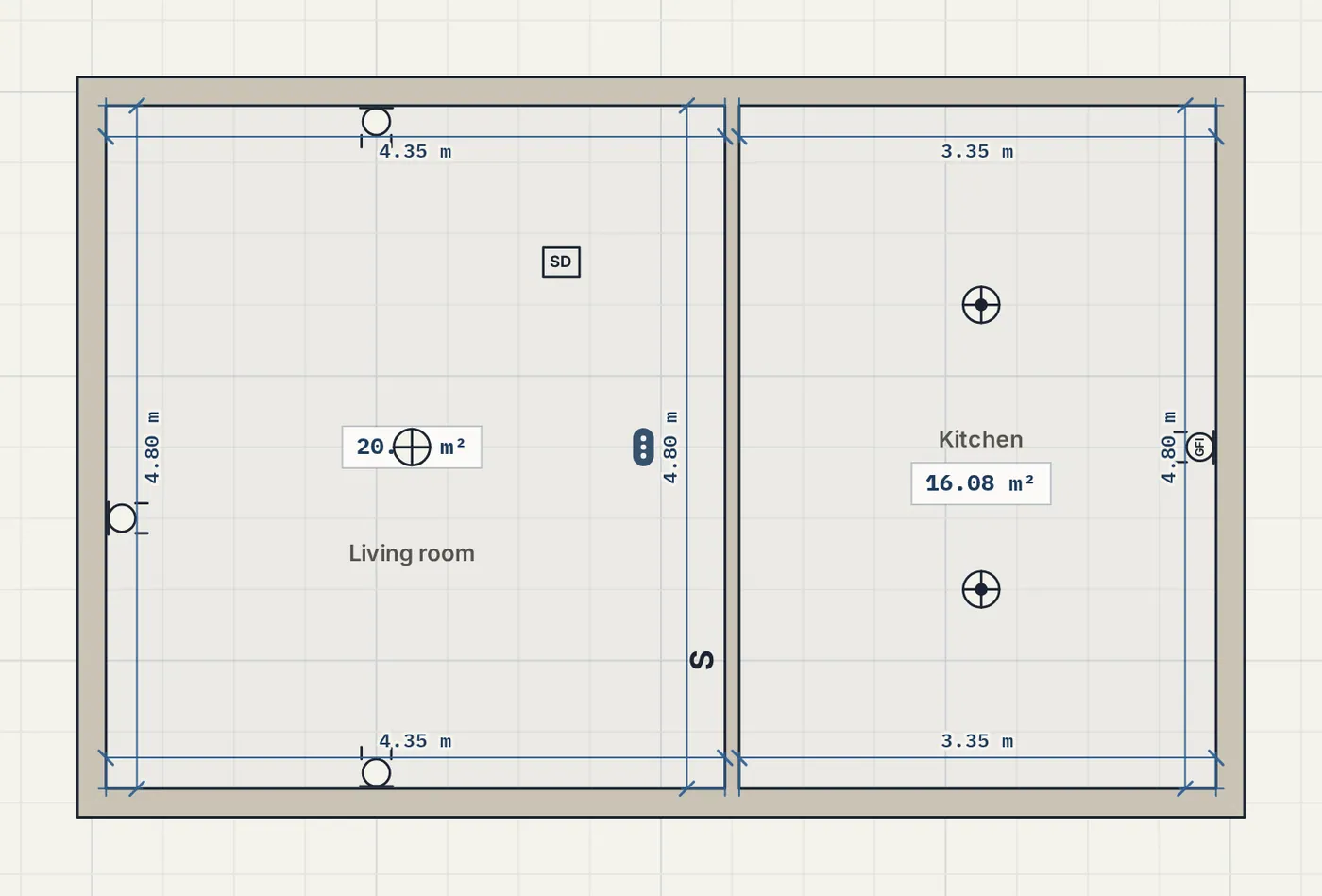
Wall devices, such as most switches, outlets and wall lights, snap flush onto the nearest wall face. Ceiling devices, such as lights, fans and ceiling alarms, drop exactly where you click.
Place the next one
Each click places one symbol, then the editor goes back to Select with the new symbol selected, so you can drag it straight away. Pick the next symbol in the Electrical panel to place another. To add a row of the same outlet, select one and press Ctrl+D (Cmd+D on a Mac) to duplicate it.
Wire devices together
Arm the Wire tool
Press E, or click Wire in the Electrical panel. The footer says Click a device, then the device to connect it to.
Click one device, then the next
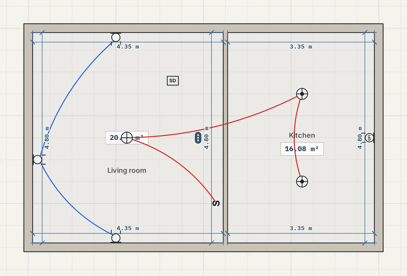
Click a switch, then the light it controls. Keep clicking devices to chain a run, for example outlet to outlet to the panel.
Read the circuits
Every group of devices joined by wires counts as one circuit and gets its own colour, so two fuses never look the same. A run does not have to reach the panel symbol.
Finish wiring
Press Esc to stop the Wire tool. Deleting a device also removes the wires attached to it.
Print the electrical plan
Open Export
Click Export at the top right. Under Include, keep Electrical wiring on and switch on Electrical legend. The legend lists every symbol used on the floor.
Hide what you do not need
Switch off Furniture & symbols or Room areas for a cleaner electrical sheet, then pick PDF and download.
Tips
- Electrical symbols keep the same size on screen at any zoom, because they are annotations, not furniture at real size.
- Turn off Electrical Wiring in Layers on the right to hide the wires while you keep drawing.
- Right-click an electrical symbol and use Select all electrical devices to move or delete them all at once.
- Use Black & white (line drawing) in Export for a plan that photocopies cleanly.
Common problems
- My outlet will not sit where I click
- Wall devices snap to the nearest wall face. Click closer to the wall you want. Ceiling devices, like lights, are free to place anywhere.
- The wire does not connect
- Both ends must be electrical devices placed with the Electrical tool. Press E, click the first device, then click the second one.
- There is no legend on my export
- Tick Electrical legend under Include in the Export dialog. It only appears when the floor has electrical symbols.
- Symbols look too big on a small room
- They are drawn at a fixed readable size, not to scale. Zoom in on the plan, or print at a larger paper size or scale.
Related topics
- Furniture libraryFind furniture and fixtures in the library, place them at real size, then move, rotate, resize, lift or swap them.
- Export & print (PDF)Download plans and elevations as PDF, PNG, SVG or a 3D model, true to scale on A4 to A0 paper, or save the whole plan as a SpacePlanner plan file.
- LayersHide or show furniture, dimensions, areas, wiring, the roof, reference images and the grid.
- Selecting and editingPick one item or many, then move, copy, group, align, lock or delete them together.
Try it on a real plan
Free, in your browser. No sign-up needed to start.